
What Are the Top Custom Resistor Types in 2026?
Custom Resistor selection in 2026 is no longer a minor specification choice. It can shape thermal stability, signal accuracy, board size, and service life. The choice is tangible: a metal-foil part beside a precision amplifier behaves differently from a thick-film chip under repeated heat pulses. BCC Research’s resistor-market analysis and Yole Group’s passive-component research offer useful market context, while manufacturer datasheets reveal the limits behind each forecast. Market figures vary by report scope, so readers should check what each study counts.
This guide compares the leading custom resistor types: thin film, thick film, metal foil, wirewound, current-sense, and high-voltage designs. It examines tolerance, temperature coefficient, power handling, noise, package options, and customization. Small details matter. A low tolerance alone does not guarantee stable readings after thermal cycling. Nor does a compact footprint automatically suit a high-pulse load.
Vishay founder Felix Zandman helped advance precision bulk-metal-foil resistor technology. A useful principle drawn from that work is: “Control the material, and you improve precision.” This is an editorial paraphrase, not a verified verbatim quotation. That distinction matters. Engineers should validate claims against test conditions, datasheets, and application requirements—not rely on a headline or a single market forecast. Some choices remain compromises; this guide makes those trade-offs visible.
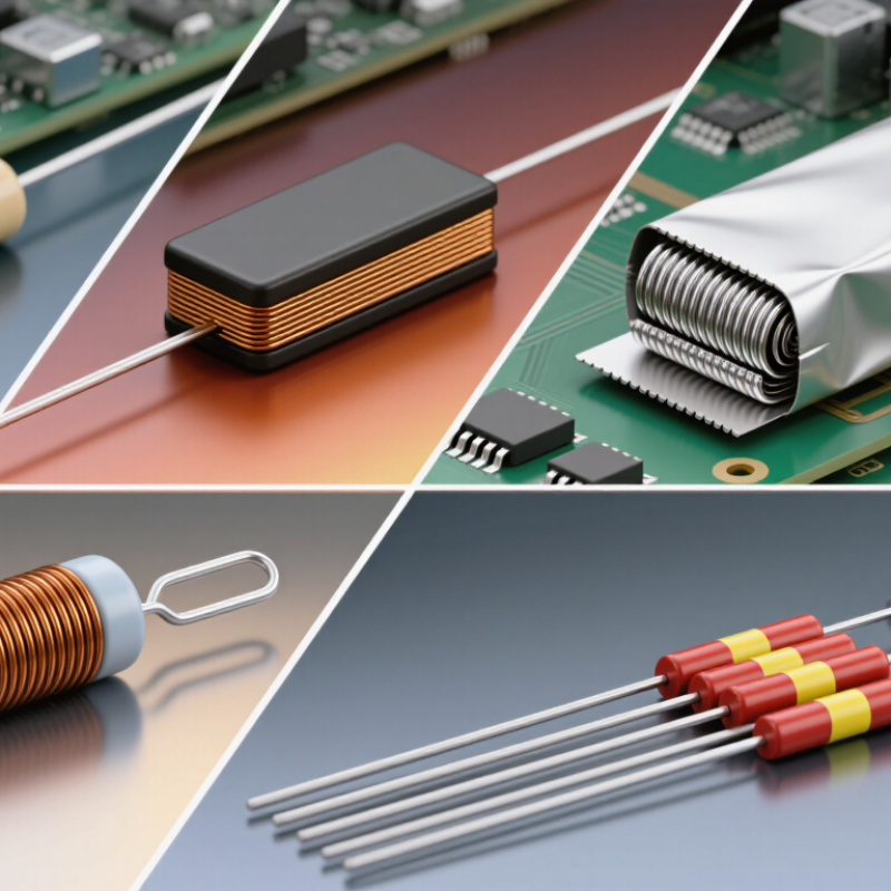
How Custom Resistors Are Classified in 2026
What Are the Top Custom Resistor Types in 2026?
How Custom Resistors Are Classified in 2026
Custom resistors are classified by how they are built, what materials they use, and the conditions they must withstand. In 2026, common choices still include wirewound, thick-film, thin-film, and metal-foil designs. Each suits different needs. Wirewound parts handle substantial power and can provide stable resistance, but their inductance may affect fast pulses. Thin-film resistors offer tight tolerances and low noise for measurement circuits. Thick-film versions are often practical for compact layouts and varied resistance values.
Construction is only one part of the classification. Engineers also specify resistance range, tolerance, temperature coefficient, power rating, package size, and operating environment. For example, a current-sensing shunt may need low resistance and predictable heating, while a high-voltage resistor needs suitable spacing and insulation. Pulse-rated and non-inductive designs address different electrical stresses. Labels can overlap, so a “precision” resistor is not automatically suitable for high power. Check the operating conditions. A small detail, such as airflow around a component, can change its actual temperature and performance.
Tips: Start with the circuit’s voltage, current, accuracy, and temperature limits. Then compare datasheets and test samples in the real assembly. It is easy to over-specify one feature and miss another.
Wirewound Resistors for High-Power Applications
Wirewound resistors remain a practical custom option when a circuit must handle substantial power and maintain stable resistance. A resistance wire is wound around an insulating core, often ceramic, then protected by a coating or housing. This construction helps spread heat, but the printed wattage rating is not a promise under every condition. It depends on ambient temperature, mounting, and airflow. Details matter.
For a custom design, share the continuous load, resistance value, operating temperature, and any short-duration surges. A resistor rated for 100 watts may need derating inside a warm, enclosed cabinet. Check the manufacturer’s temperature curves and leave room for heat to escape. Secure mounting matters too; loose contact with a heatsink can raise component temperature. That is easy to overlook.
Wirewound parts can also introduce inductance, which may affect fast-switching or high-frequency circuits. For those cases, ask about non-inductive winding options and verify performance in the actual circuit. Measure temperature after the assembly reaches steady operation, not just during a brief bench test. A little extra margin often prevents trouble, though it costs space and sometimes more. The best custom resistor is the one that fits the real thermal and electrical conditions, not merely the schematic.
Top Custom Resistor Types in 2026: Power-Rating Examples
Wirewound and thick-film power resistors are available in high-power configurations, making them useful for power loads and braking circuits. Values shown are representative commercially available ratings, not universal limits; actual power handling depends on the specific design, mounting, cooling, and operating temperature.
Metal-Film and Foil Resistors for Precision Circuits
In 2026 precision circuits, metal-film and metal-foil resistors solve different problems. Metal-film parts suit stable, cost-conscious designs, such as amplifier feedback networks and sensor inputs. Foil elements are useful when temperature drift and long-term stability matter more than price. Small drift matters. A 10 kΩ sensing path can shift enough to affect a carefully calibrated measurement.
IEC 60115-1:2020 specifies test methods and performance requirements for fixed resistors, including tight tolerance classes such as 0.1%. That figure is a useful selection point, not a promise of accuracy across temperature or service life. Metal-film parts can be specified at tight initial tolerances, while foil designs can offer exceptionally low temperature coefficients. Check the datasheet’s TCR, load-life drift, and power derating; the headline tolerance alone is not enough.
Measurement practice matters, too. NIST Technical Note 1297 explains that expanded uncertainty uses a coverage factor; k = 2 corresponds to approximately 95% coverage under stated assumptions. This is a reminder to include instrument and calibration uncertainty when validating a precision circuit. Foil may reduce resistor drift, but it cannot fix poor thermal layout. I have seen designs overlook nearby heat sources. It is an easy detail to miss.
What Are the Top Custom Resistor Types in 2026? — Metal-Film and Foil Resistors for Precision Circuits
| Resistor Type | Element Construction | Typical Tolerance | Typical TCR | Key Strengths | Common Precision-Circuit Uses | Design Considerations |
|---|---|---|---|---|---|---|
| Precision Metal-Film | A thin resistive metal-alloy film deposited on an insulating ceramic substrate and trimmed to value. | About ±0.1% to ±0.01%, depending on the part and specification. | Common precision grades are around ±5 to ±25 ppm/°C. | Good accuracy, low noise, and a useful balance of stability, size, and cost. | Signal conditioning, instrumentation, feedback networks, and precision voltage dividers. | Check the specified temperature range, power derating, voltage coefficient, and long-term stability for the intended operating conditions. |
| Bulk Metal-Foil | A patterned resistive metal-alloy foil bonded to a ceramic substrate; the foil geometry is designed for stable performance. | Common precision options range from about ±0.1% down to ±0.01% or tighter for selected designs. | Specialized parts can reach approximately ±0.2 to ±2 ppm/°C. | Very low TCR, strong long-term stability, and low sensitivity to changes in ambient temperature. | High-accuracy references, bridge circuits, precision measurement equipment, and calibration systems. | Often costs more than general-purpose film parts. Allow for self-heating, thermal gradients, and the specified mounting conditions. |
| Thin-Film Chip | A thin resistive film deposited on a ceramic chip, with the resistance pattern formed by trimming or photolithographic processes. | Common precision grades are approximately ±0.1% to ±0.01%. | Often specified in the range of about ±5 to ±50 ppm/°C, depending on construction and value. | Compact size, close matching options, and good performance in surface-mount assemblies. | Compact instrumentation, precision analog boards, and resistor networks where board space matters. | Confirm pulse and surge ratings, soldering requirements, and whether the application needs individual resistors or a matched network. |
| Matched Thin-Film Network | Two or more thin-film resistors fabricated on a shared substrate to improve ratio tracking and thermal matching. | Individual-element tolerance and ratio tolerance are specified separately; precision ratio options can be tighter than standalone parts. | Absolute TCR is design-specific; tracking TCR is often the more important specification for ratios. | Improved channel-to-channel matching and reduced relative drift compared with separately mounted resistors. | Differential amplifiers, ADC front ends, gain-setting circuits, and precision dividers. | Specify ratio tolerance, tracking TCR, operating temperature, and layout or package requirements explicitly. |
| Precision Current-Sense Shunt | A low-resistance metal-alloy element, commonly implemented as a stamped or deposited resistive element with suitable terminals. | Precision versions are commonly available around ±1% to ±0.1%; tighter options depend on design. | Varies by alloy and construction; low-TCR versions are available for measurement applications. | Designed for accurate current measurement, with low resistance and defined power handling. | Battery monitoring, power conversion, motor control, and current-feedback circuits. | Account for power dissipation, pulse loading, Kelvin connections, PCB copper effects, and temperature rise. |
Specifications shown are representative ranges, not guaranteed values for every design. Actual performance depends on resistance value, package, operating conditions, and the supplier’s datasheet.
Shunt Resistors for Current Sensing
Shunt resistors measure current by producing a small voltage drop across a known resistance. In a custom design, the resistance value must balance signal strength, power loss, and measurement range. A 1 milliohm shunt, for example, produces 10 millivolts at 10 amperes. That signal is measurable, but nearby switching noise can distort it. Choose a suitable resistance, then check the expected current and pulse conditions. Four-terminal, or Kelvin, connections help keep lead resistance out of the measurement. Small details matter.
Tips: Check the resistor’s power rating against continuous and peak current, not just the average load. Review tolerance and temperature coefficient, too. Heating can shift resistance and introduce measurement error. Place sensing traces close to the resistor’s dedicated terminals.
High-side sensing preserves the load’s ground connection, but its amplifier must handle the common-mode voltage. Low-side sensing is often simpler, though its voltage drop can disturb the ground reference. Layout and amplifier choice should match the circuit. For fast current changes, consider parasitic inductance and bandwidth; a low resistance alone does not guarantee a clean reading. Bench testing under realistic load helps expose problems that calculations may miss. A tidy schematic can still hide a noisy measurement.
Thick-Film and High-Voltage Resistors for Specialized Designs
In 2026, custom resistor choices often start with thermal and voltage limits, not catalog labels. Thick-film resistors suit compact control boards, sensor modules, and power supplies where cost and layout matter. Their resistive layer can be tailored for resistance, size, and pulse demands. However, performance varies with substrate, trimming, and operating temperature. That variation deserves testing; it is easy to overlook.
High-voltage resistors address a different challenge: maintaining stable resistance under substantial electrical stress. Designers may use series resistor strings to spread voltage and reduce localized heating. Creepage distance, clearance, coating, and board contamination also affect real-world performance. A component’s rated voltage alone does not guarantee a reliable assembly. Check working voltage, pulse energy, temperature rise, and the surrounding layout together.
Tips: Confirm the maximum continuous voltage and expected surge conditions with measured data. Leave adequate spacing, then inspect the board after thermal testing. If a resistor runs cooler than expected, that is useful—but it does not prove long-term stability. Recheck the design across realistic operating conditions.
