
10 Tips for Choosing the Right DC Servo Drive
Choosing the right dc servo drive can determine whether a machine runs smoothly or struggles under real production demands. The decision involves more than matching voltage and current ratings. Engineers must examine motor feedback, load inertia, acceleration time, braking needs, communication protocols, and thermal conditions. A drive that looks suitable on paper may still overheat beside a conveyor or lose position during rapid indexing.
Robotics professor and author Peter Corke describes a robot as “a machine that can sense, think, and act.” That idea applies directly to servo selection. The motor creates motion, the encoder provides awareness, and the drive interprets commands while correcting errors. A reliable dc servo drive should therefore fit the entire motion system, not just the motor label. Practical testing matters. Watch the shaft during startup. Listen for hunting. Check the cabinet temperature after several hours. Small details matter.
This guide presents 10 practical tips for comparing drives, including control modes, feedback compatibility, tuning functions, overload capacity, safety features, and long-term support. It also considers installation space and service access, because technicians rarely work in perfect conditions. No checklist replaces engineering judgment. A clean specification sheet can still hide poor performance. That is the trap. Some recommendations may need adjustment for older machines, unusual loads, or incomplete documentation. Readers should verify ratings with manufacturers and test the selected dc servo drive under realistic operating conditions before committing to production.
Define the Motor’s Voltage, Current, and Power Requirements
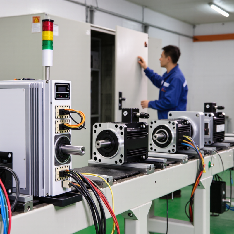
Choosing a DC servo drive starts with the motor’s electrical requirements, not the drive’s advertised feature list. Record the motor’s nominal voltage, continuous current, peak current, and rated power. Use the motor datasheet and verify the values with a multimeter and controlled test setup. Small errors here can create overheating, unstable motion, or repeated drive faults.
Voltage must match the motor’s operating range and the available power supply. A 24-volt motor may behave poorly when the supply drops during acceleration. Current selection needs more care. Continuous current supports normal load movement, while peak current handles short events such as starting, lifting, or rapid direction changes. Check the peak duration specified by the motor and drive. A larger current rating is not automatically safer.
Calculate power with voltage multiplied by current, then examine the machine’s duty cycle. A motor moving a 15-kilogram carriage every few seconds produces a different thermal demand than one running continuously. Leave practical capacity for friction, payload changes, and supply variation. Avoid excessive oversizing, because poor matching can reduce control sensitivity and increase cost. A neat spreadsheet is not proof. Real loads are rarely neat. Test acceleration, braking, and low-speed holding under realistic conditions. Braking can return energy to the DC bus, so the drive may need suitable regeneration handling. I have seen a system pass a bench test, then trip after ten minutes on the machine. Temperature revealed what the calculations missed.
10 Tips for Choosing the Right DC Servo Drive - Define the Motor’s Voltage, Current, and Power Requirements
| Tip | Requirement to Define | Example Motor Data | Recommended Drive Capability | Selection Guidance |
|---|---|---|---|---|
| 1. Confirm Rated Voltage | Motor rated voltage and the available DC bus voltage | 48 VDC motor; 36–60 VDC supply range | Continuous bus range must include 48 VDC; peak operating limit above the maximum supply | Select a drive whose continuous and maximum DC input ratings safely cover the motor and power supply. |
| 2. Calculate Continuous Current | Current required during normal operation | 8 A continuous motor current | At least 8 A continuous output; 10 A or more provides practical margin | Continuous current should meet the motor’s thermal requirement without relying on the drive’s short-term peak rating. |
| 3. Check Peak Current | Short-duration current needed for acceleration or load changes | 16 A peak for 2 seconds | At least 16 A peak for the required duration | Verify both the peak current value and the permitted peak-time duty cycle in the drive specifications. |
| 4. Verify Motor Power | Electrical power at the motor’s rated operating point | 48 V × 8 A = 384 W nominal electrical input | A drive rated for approximately 400 W or more at the selected voltage | Allow for motor losses, drive losses, acceleration demand, and variation in the DC supply voltage. |
| 5. Match Speed and Back EMF | Maximum speed and generated voltage at that speed | 3,000 rpm maximum; back EMF must remain below the available bus voltage | Voltage headroom for regulation at maximum speed | Insufficient voltage headroom can reduce high-speed torque and prevent the motor from reaching its commanded speed. |
| 6. Size for Acceleration Torque | Current required to accelerate the combined load inertia | 12 A acceleration current for a 0.5-second ramp | Peak output capability of at least 12 A, with suitable thermal recovery | Use the reflected load inertia, acceleration time, and torque constant to estimate acceleration current. |
| 7. Consider Regenerative Energy | Energy returned to the DC bus during deceleration or overhauling loads | Approximately 80 J per rapid stop | Built-in regenerative handling or an external braking resistor rated for the duty cycle | Check bus overvoltage limits, braking resistor resistance, pulse power, and average power requirements. |
| 8. Select the Feedback Interface | Feedback type, resolution, and electrical compatibility | Incremental encoder; 2,500 pulses per revolution | Compatible encoder input with adequate frequency and voltage support | Confirm encoder supply voltage, signal levels, maximum input frequency, and required position resolution. |
| 9. Check Control-Loop Bandwidth | Required response speed for the application | Positioning cycle: 100 ms; moderate disturbance rejection | Adjustable current, velocity, and position loops with stable tuning at the target load | High-speed machinery may require faster current-loop response and carefully configured velocity and position gains. |
| 10. Validate Thermal and Protection Ratings | Ambient temperature, enclosure conditions, overload, and fault protection | 35 °C ambient; 60% average load duty cycle | Continuous rating at the actual installation temperature with overcurrent, overvoltage, and overtemperature protection | Derate the drive when required by ambient temperature, restricted airflow, enclosure size, or high-duty operation. |
| Example sizing basis: a 48 VDC brushed DC servo motor requiring 8 A continuously and 16 A for short acceleration periods represents approximately 384 W of nominal electrical input power. Final selection should be confirmed using the motor datasheet, load profile, duty cycle, and installation conditions. | ||||
Related Posts
-
Why Choose a DC Servo Drive for Industrial Automation?
-

Top 10 Benefits of Using DC Servo Drives in Industrial Applications
-

Top Small DC Motor Applications and Buying Guide for Beginners
-

How to Choose the Right Electric Servo Motor for Your Project?
-

Exploring the Future of Robotics: How Servo Motor Drivers Transform Automation
-
7 Reasons Why Your Factory Needs an AC Servo Motor Today